Showing posts with label pcb. Show all posts

Sunday, 24 April 2011

Mr. JP lives again!

Three weeks ago I did one of the strangest things I've ever done - and probably ever will do. I bought a Roland Jupiter-8 on Ebay, but instead of sending it back home to Norway, I sent it to a very nice person I had never met and never talked to :-D

I did this for several reasons. The two main reasons being that I knew she would love to have a JP-8 and that I find her compositions really cool.

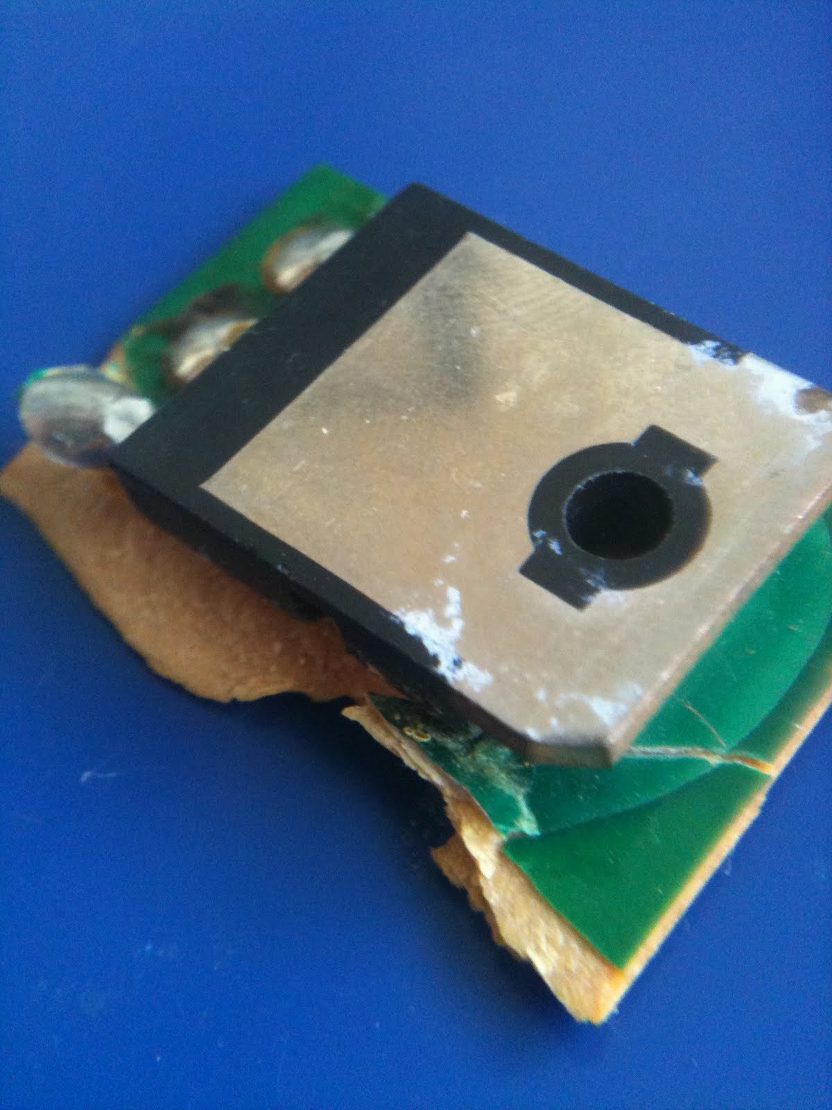
Also, I felt, that buying such a synth unseen/unheard, it would be a good thing to have it checked by a pro before shipping it back here. It turned out that this was a really good idea, as somehow a PCB inside had broken while the synth was in transit from Kansas to Texas. Luckily, the person who received it, knew just where to go to get it fixed :) So as of yesterday, my Jupiter-8, fondly named Mr. JP, is once again able to create those great 80-s sounds!


A big thanks to the people at Switched on synthesizer repair shop in Austin, TX. They fixed both the broken PCB as well as some loose cables and two broken keys :-D

Now I am looking forward to some cool videos and compositions on Youtube, featuring Mr. JP. The synth will stay in Austin at least for a year. In the meantime I can remove the JP-8 from my shortlist of synths I need to get :)

Here are some photos:


Friday, 8 October 2010

Fall is here - finally!

...not that I enjoy fall that much, but it means I have so much more time to spend indoors without feeling bad about it. And so loads of things are going on at the moment:

Today I got the box and side caps for the drum machine (in fact, I got three boxes, because it was so much cheaper per box if I ordered more than one). Big thanks to Shah for sending them to me, saving me several thousand kroners! The box looks incredibly good - so good that I won't publish any pics before the machine is fully assembled :-)

I am a little bit disappointed with the powder coating though, as it seems they have missed some spots and not put enough powder in other places. But that is me being picky, the over all result is very good. Tomorrow I'll start measuring everything and finish up the panels I'm going to ordered from schaeffer. Hopefully they won't take as much time to create.

Last week I ordered a silk screen kit - a really good one - capable of printing in two colors. It set me back more than a thousand dollars, so I really hope it does the job...

Monday I received a pcb for the "fat controller" midi-to-CV converter, a 15-output controller for my modular project. I have already ordered all the necessary parts, some quite special, from Mouser, DigiKey, Farnell and Elfa. At the same time I ordered the missing connectors and switches for the two extra boxes, with the exception of five midi connectors.

I have also finished soldering about half of the pcbs for the modular synth. Now I have to decide what format to make it - large synthesizers.com, old school, or small, 19-inch eurorack. I have found some really nice rack rails from tiptop audio, and a place in the US willing to sending the to me, if they can find an envelope large enough.

Hmm, anything else? Probably, can't remember.

Oh, btw, gf started working last friday! AND she got me a function generator for my birthday - something I really needed for tuning the modular :-)

Friday, 3 September 2010

Fall is here

Fall is here, and it's time to get this thing working! Today I've found the last (?) glitch in my PCB design - I've forgotten to connect the mixing bus'es to the headphones amplifier. This was the reason I could not get any sound. Fixed that and it works perfect.

Also, I am getting some noise from the crash symbal. Tried to switch the crash and ride cybal rom chips, but the noise still came from the crash. Thus, I believe I need to get a new rom chip.

This means that I have to purchase:
1 head phones pot
1 rom chip, 24c256.

As for other electronics, I think the only thing missing is the red backlight for the LCD screen.

The bottom part of the box is (hopefully) on its way from the US now. Next up is a silk screen set...

Oh, and I've soldered several of the modular synth modules too - still need to make a Midi2CV converter though, in order to test them.

Saturday, 15 November 2008

Encoder/leds circuit v1

I've started work on the led dial. So far I've left it to the users to decide if they want to use i2c or any other way of inter-ic communication, all data transmission pins are available as pin outs.

I've also added a mikroelektronika-compatible programming interface to enable programming of the chip after soldering.

The chosen mcu, pic18F2431, contains both a quadrature decoder and an internal ocillator, making the number of external components very low.

I have not yet tried the programming circuit like this, so it may have to be changed.

The schema:


The PCB. Dimensions 29 x 29 mm:


I still have some work to do on the footprint of the encoder, and of course have to find a way to solder this since the mcu, resistors and capacitor are SMDs

Wednesday, 8 October 2008

Oh, how I hate hardware bugs...

I must have misplaced my head while designing the keyboard PCB.

The last two days my girlfriend and I have

1) Checked all the ICs involved in the rotary encoder circuit
2) Checked the functions of the rotary encoders
3) Checked the PCB routings for any errors or broken paths.

We didn't find any errors on the ICs, they all performed flawlessly on the bread board.

As for the encoders, they seem to be of different kinds. The tempo encoder seems to stay permanently connected to +5v and send out pulses of 0V (or rather, it varies with the position of the encoder), while the mode encoder stays at 0 and sends out pulses of +5v. Not sure if this is a problem, but it has to be checked.

The routing, however, is a different story. First of all, although it is not possible to see why when inspecting the PCB, the connection between the tempo encoder and pin 5 on the left flip flop IC is broken! This may have happened when the IC overheated earlier.

More important though, I have not routed +5v and ground to the ICs! This is a mistake made in Gschem, the software I used when designing the circuits, I simply must have forgotten to attach the necessary pins to the power connector :-(

So, right now I have to:
1) swap the tempo encoder for one similar to the mode selector one.
2) connect pin 5 on the left flip flop to pin 1 of the tempo encoder
3) connect pin 14 on the right flip flop to pin 2 of the tempo encoder (5v)
4) connect pin 7 to pin 8 on the right flip flop (ground)

...then we'll see what happens.

Sunday, 28 September 2008

Midi controller 4 v1.0 PCB received

Resent events: turned 30 yesterday... Sigh. I would have hoped to be finished before turning 30, but noooo.

I also received the new PCB for the controller. I've already populated it, testing starts tonight. I have great expectations for this new version. However, I still haven't tried the digital giver circuits, so perhaps I'm in for a version 1.1 of MC4 as well? Only time will tell.


Tuesday, 11 March 2008

New controller finished

Except for finishing touches and error checking, Midi controller number 4, v1.0 is finished! This uses a single 40 pin mCU instead of two smaller ones, which made it a challenge to route all the paths in the small space available. It looks promising though.

I just tought of another idea for a dual mCU version though. Perhaps it would be possible to use i2c for communication between the devices? In that case, I would be able to use hardware instead of software-emulated com, but I'm not sure about the speed of the i2c bus. Will have to research this later if I get into trouble running everything on a single mCU (It should not be a problem, but who knows...).

Here is a pic of the new PCB:

Saturday, 2 February 2008

Keyboard PCB problems

I have made a crucial mistake on the keyboard PCB. The second line of instrument buttons is connected to select line 1 instead of 2, meaning both rows map to the same keys :-( This has to be fixed by cutting a line on the keyboard and connecting it manually to select line 2. Bummer.

Also, SEL9 and 10, going to the keypad, are not working properly. This could be just the cable though.

Wednesday, 26 December 2007

(almost) finished keyboard

This is a big day for me. I've powered up the keyboard for the first time. I have not yet connected the pulse givers (dials) as the perspex pieces were not correct. I also have not been able to test all leds as the 2N3906 transistors I use are not in stock at Elfa. I do, however, suspect that using the transistors, at least in my config, is a waste, it seems the power is drawn from the controlling circuit, not trough the transistor.

The 7 leds that I've been able to connect work flawlessly, in both red and green modes. I've also (temporarily) connected the PCBs to the aluminium from Schaeffer. Some pics below.


Sunday, 25 November 2007

Finished soldering the keypad


The keypad is finished, except for the headers/connectord. It looks very good, but one key is missing. I can't remember if i did this on purpose or if it is accidental. It doesn't matter too much but is a bit strange none the less...

PCB pics

Keyboard front/back:


Output pcb front/back:


Keypad pcb front/back

PCB pics

Circuit boards:

Keyboard front/back:


Output pcb front/back:


Keypad pcb front/back

PCBs have arrived

I got the PCBs from Olimex friday, and as last time they look great! They even silk screened the back side of the keyboard pcb :) I have discovered a small error on the keypad card - the flat cable connector is on the wrong side of the board, meaning pin 1 = pin 2, pin3 = pin4 etc. This will not pose a problem if I solder the cable directly to the board, it's just a bit annoying. Perhaps it's possible to fix it in software, I'll have to check that.

Pics will be up soon.

Monday, 5 November 2007

All pcbs shipped to Olimex for production

I have finally finished the necessary PCBs and sent them to Olimex for production. Big thanks to the teams making Gschem and PCB for Linux, without them I would not be able to produce the 320mm wide keyboard PCB.

I've created and ordered three PCBS:
1) The main keyboard (steps, tempo, edit, instrument select)
2) The keypad
3) A new output board, including a headphone amp.

The total price for the PCBs, including shipping, is $193,20

Keyboard pcb design rev. 1

I've finally finished the initial PCB design for the main part of the keyboard. It seems to be a little cramped however, so I have to redo some of it. But at least it seems possible to connect all the dots ;-)

Have a look at an image here:


To hell and back

Last christmas, I broke my '09, but this very great day, I finally got it working again...

To make a short story long: While trying to figuring out what was wrong with the hihat and crash cymbal sample circuits, and after borrowing an oscilloscope, I managed to put PCB001 on top of my keys, thus short-circuiting something and blowing the fuses. I probably broke some components as well, because as I replaced the fuses (with two pieces of wire, smart eh?), some of the opamps got really hot. I tried to replace the hot opamps (I had no quick way of figuring out if they were broken or not, and I didn't have enough opamps to replace all of them. This didn't work very well, as other opamps quickly overheaded as well. In a stroke of genius, I decided to disconnect PCB002 as well as all the potmeters, to prevent damage to those as well. This, I've understood retrospectively, only made things worse, and ended with the 7915 voltage regulator exploding. This was the 22nd of December, and got me rather depressed.

So, for the rest of the year I left the machine untouched. The first week of 2007 I decided to try to fix it in a more scientific way. First, I built a astable multivibrator, to test the Opamps. I found 12 defect opamps on PCB001 and none on PCB002, leading me to believe that PCB002 was left untouched by the forkup.

Next, I tried to find a way to test the transistors, but after realising the risk of ruining the PCB while unsoldering three legs at the same time, I ended up just clipping away the transistors and replacing them with new ones instead. So, I replaced all 549 and 559 transistors on PCB001, as well as testing the rest of the transistors. Next, I measured all resistors and diodes, unsoldering one leg if the measurements were odd. I ended up replacing 5 diodes in the process. I also checked that none of the capacitors had failed short circuiting anything. Finally, I checked the voltage regulators, rectifier and replaced all logic ICs and opamps.

To prevent new disasters, I then mounted the pcbs, connectors and front panel to a piece of MDF.

Thursday last week I finally worked up enough courage and confidence to power up the drum machine again. And it worked! (Or, at first nothing happened, but I quickly realised that all level pots were at 0).

So began the task of fixing the hihat and crash cymbal. Using the oscilloscope, I figured out that the hihat seemed to be working, except it didn't let any sound through to the output. After measuring (and listening - I built a small head phone amp and connected it to various parts of the hihat circuit) my way through the circuit, I decided to replace three transistors. Spot on - it fixed the hihats :-)

Finally, the cymbal. This is where I expected some real problems. As mentioned previously, I managed to break the PCB while replacing an IC socket. I started out measuring the various connections between parts. I found several errors, only to discover that two of the gates in Trevor's schema are wrongly labeled (U61D should be U66A, and U66A is really U66D).

The whole circuit checked out OK, but upon closer inspection, the connection between the potmeter and the PCB seemed a little fishy. I checked the crash tune connector, and guess what - the connection crimp was so flat it didn't touch the PCB part! Once that was fixed, everything worked as it should.

So, there you go - after a few sleepless weeks ( ;-) ) everything works as planned - the sound circuits are finished except for the head phone amp - and I am a happy little vegemite again :-D
Good news everybody!

I have worked out nearly all the errors now. The single-channel problem was due to a broken down line mixer in my rig. The low output level must be somewhere between the output from PCB005 and the stereo output (i.e. in the mix amp) as all separate outputs have a very high output level :-)

As for the two missing sounds (hi-hat and crash cymbal), I DID partially break the PCB while trying to de-solder a socket (stupid, I know, and I promise I've learned my lesson: NEVER try to de-solder a $1 part if you may break a fully populated rare PCB... *sigh* - and I was very much aware of the risk beforehand, but it was late and I had misplaced the DIL socked).

Guess it should be possible to fix both errors shortly!

Ahh... :-)

On another note - the sounds are rich and beautiful. Big thanks to Trevor Page and everyone else involved in creating the clone!

Controller PCB and parts arrived

The PCBs for the controller (Midi, keyboard/leds and LCD display) arrived from Olimex today. It looks good, especially for the price payed (about $35 for two PCBs). The edges are not straight cut but it doesn't matter as long as the mounting holes are in the right place.

I've discovered that the holes for the crystal are very small but it seems to work. The LCD contrast potmeter will not fit but I'll guess I can make it work somehow.

All the necessary logic for the controll of the digital parts of the drum machine was supposed to be included on the PCB. I have however discovered that the rotary encoders I intend to use work differently than the ones on my prototype, so some logic has to be added to the keyboard as well.


The last big order of parts also arrived today, from Mouser and ELFA:


First 'product' - das Kontroller

In addition to the drum machine, I promised a friend of mine to build him a specialized midi controller (actually, it was the controller that kicked off everything). I spend a lot of time working on the controller, which uses the same keyboard logic as the prototype and the drum machine.

The controller was finished the 11th of september 2006, exactly one year after we started working on it, and was named 'das Kontroller' as an inside joke refering to the blank-keys-keyboard das Keyboard.

I created a controller PCB using the free (but proprietary) PCB editor from EasyPCB.com, and had them etch me three PCBs:


This became the 'brain' of das Kontroller and worked flawlessly. It contained a midi interface, a serial rs232 interface as well as possibilites to connect a standard character LCD. The LCD has not been tested but everything else works flawlessly.

One thing was missing from the PCB though. Due to the way EasyPCB prices their PCBs, I desided that I would not have room for the keyboard-scanning ics on the controller, which only measures 6 * 10 cm.

For the keyboard, I designed (again in Illustrator...) an approximately 30 * 20 cm PCB, which I transfered to a blank PCB using photo paper and a laser printer, and etched at home. I then drilled about 1500 holes by hand, to fit close to 100 keys ands LEDs, and 8 potentiometers (faders). Unfortunately, I screwed up the layout somewhat and had to do some modifications using extremely thin modification wires (click for large images):


After fixing the design errors, das Kontroller now works as intended. The total price ended at about NOK 7000 (approx USD 1100), of which the majority was the enclosure and keys.

The finished result can be viewed here:
http://www.upland.no
here
and here